Potentiometer with Angular Servo
Introduction
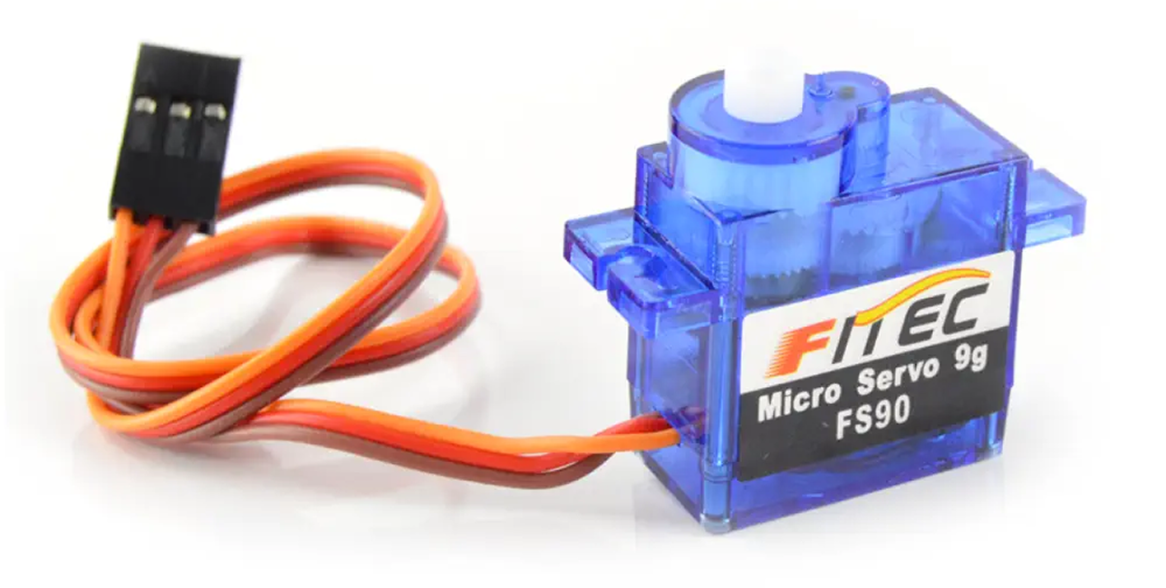
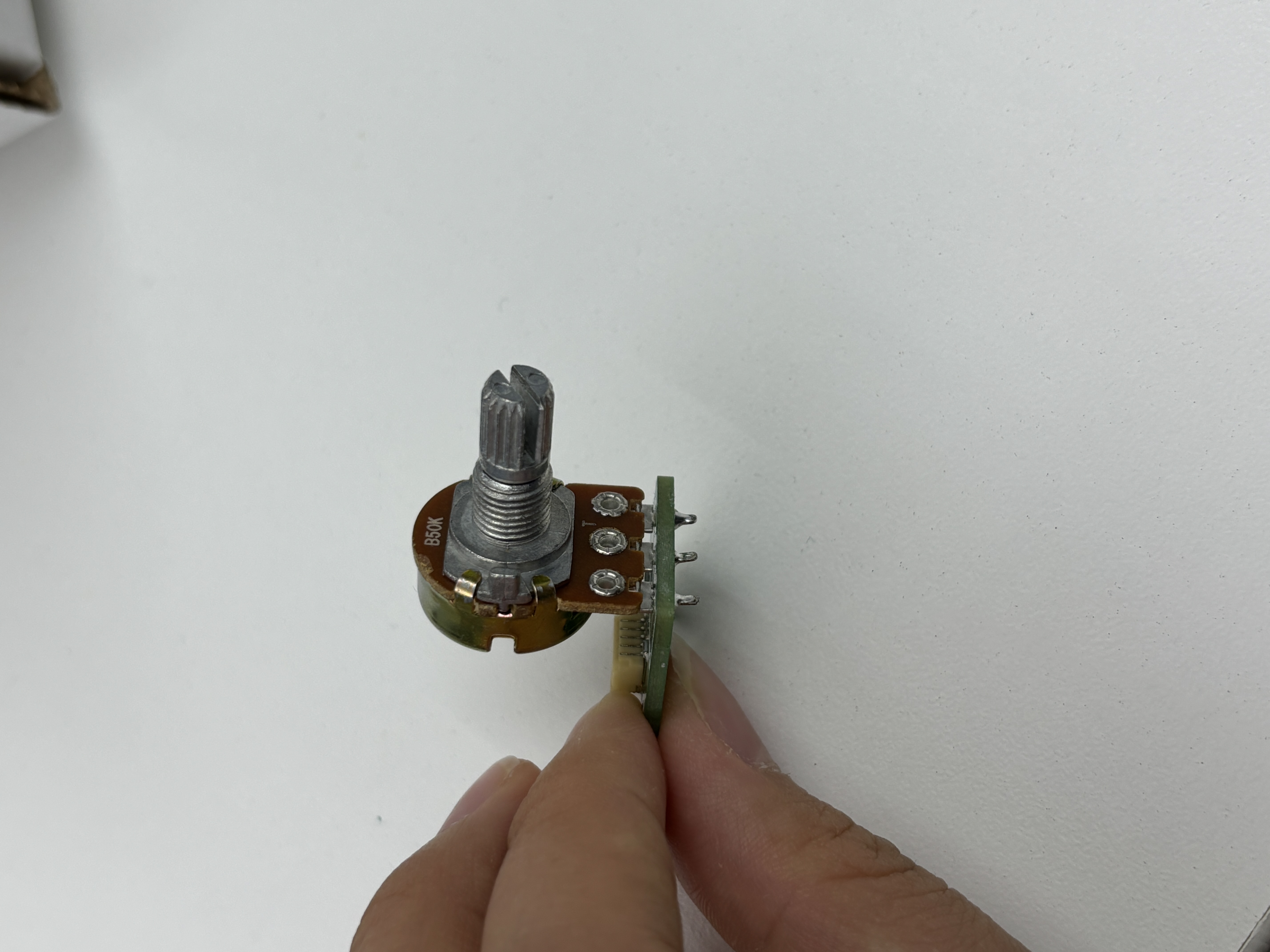
In this example, the angular servo motor moves based on input from the potentiometer. The measured potentiometer value is mapped to a corresponding angle, which is then used to position the servo.
Circuit Assembly
Connect the potentiometer and servo motor to any digital pin. In our example, we're using A1/A0 for the potentiometer and D5/D4 for the angular servo motor.
The analog pin that you connect your potentiometer to corresponds to a particular analog in your code. We're using A1/A0, which is represented as A1 in the code.
• A1/A0 → pot_pin = A1;
• A3/A2 → pot_pin = A3;
• A5/A4 → pot_pin = A5;
• A7/A6 → pot_pin = A7;
The digital pin that you connect your angular servo with corresponds to a digital pin value on your code. We're using D5/D4, which corresponds to 5. You can remix yours to look like this:
• D11/D10 → servo_pin = 11;
• D9/D8 → servo_pin = 9;
• D7/D6 → servo_pin = 7;
• D5/D4 → servo_pin = 5;
• D3/D2 → servo_pin = 3;
• D1/D0 → servo_pin = 1;